Tank Circuit
New Member
I am getting interested in designing my own version of a digitally controlled metal detector. I know this is a daunting task, so I wish to start out with a very simple analog metal detector from days gone bye. I have this old T/R (I/B) metal detector and I am in the process of reverse-engineering the circuit. I have drawn out the schematic and the only thing left is to determine how the search coil is wound. I am hoping that there is someone with a lot more experience on how manufacturers wire their search coils since I am hitting a snag.
If you know why I am getting the anomaly during my tests please chime in and assist me while I am building my replicant version.
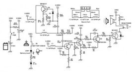
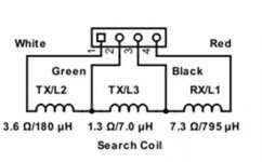
There are 4 wires coming from the search coil, and after checking each one, I discovered that they are all connected to each. There is also a 5th wire present which is attached to the RF metal shield and it is open to all other wire connections. This coil’s 4 active wires consist of a red, green, black and white wire. After a comprehensive test of the coil’s resistance and inductance measurements, I concluded that it probably consists of two large coils and they are likely are wound in the “Double-D” configuration. I have added an insert showing how I visualize the various sections of the search coil are connected on the schematic diagram and I have added a chart showing the measured resistance and inductance on every wire (the search coil was out-of-circuit).
In the schematic, I show that the transmit coil section is made up of L2 and L3 and the receive coil is L1. I realize that measuring inductors with a DMM in resistance mode is not ideal, but during my tests, I found when testing L3 it was acting differently than what I would expect. I figure that the total resistance across all the coils would decrease a little if the wires of L3 were shorted together. When I measure the resistance between the white and the red wires, I get 9.6 Ω even if the green and black wires are shorted together or not. I checked every possible connection and read their resistance while shorting the other two wires together and the measurement never changed at all. This makes me question if I have the configuration correct.
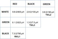
I figured that perhaps L3 was wired in a delta or wye configuration. So I broke out the inductor tester and it shows that the total inductance drops like expected when I short out L3. The total inductance drops 40 µH from 900 µH to 860 µH. So now I have my inductance meter showing that these coils are in series and my Fluke DMM disagreeing. I have assembled a simple graph showing the resistance and inductance between the various connections.
The two outside wires (red and white) naturally have the highest resistance and inductance. I realize that if I add the sum of all the coils the total will not match. I also know that depending upon the direction on the winding it will either add or subtract to the inductance.
As I mentioned before. If I measure the resistance across the red and white wires, I get the 9.6 Ω reading. If I short the green and black wires together, the resistance remains the same.
If I measure the inductance across the red and white wires, I get the 900 µH reading. If I short the green and black wires together, the inductance drops to 860 µH.
If you know why I am getting the anomaly during my tests please chime in and assist me while I am building my replicant version.
There are 4 wires coming from the search coil, and after checking each one, I discovered that they are all connected to each. There is also a 5th wire present which is attached to the RF metal shield and it is open to all other wire connections. This coil’s 4 active wires consist of a red, green, black and white wire. After a comprehensive test of the coil’s resistance and inductance measurements, I concluded that it probably consists of two large coils and they are likely are wound in the “Double-D” configuration. I have added an insert showing how I visualize the various sections of the search coil are connected on the schematic diagram and I have added a chart showing the measured resistance and inductance on every wire (the search coil was out-of-circuit).
In the schematic, I show that the transmit coil section is made up of L2 and L3 and the receive coil is L1. I realize that measuring inductors with a DMM in resistance mode is not ideal, but during my tests, I found when testing L3 it was acting differently than what I would expect. I figure that the total resistance across all the coils would decrease a little if the wires of L3 were shorted together. When I measure the resistance between the white and the red wires, I get 9.6 Ω even if the green and black wires are shorted together or not. I checked every possible connection and read their resistance while shorting the other two wires together and the measurement never changed at all. This makes me question if I have the configuration correct.
I figured that perhaps L3 was wired in a delta or wye configuration. So I broke out the inductor tester and it shows that the total inductance drops like expected when I short out L3. The total inductance drops 40 µH from 900 µH to 860 µH. So now I have my inductance meter showing that these coils are in series and my Fluke DMM disagreeing. I have assembled a simple graph showing the resistance and inductance between the various connections.
The two outside wires (red and white) naturally have the highest resistance and inductance. I realize that if I add the sum of all the coils the total will not match. I also know that depending upon the direction on the winding it will either add or subtract to the inductance.
As I mentioned before. If I measure the resistance across the red and white wires, I get the 9.6 Ω reading. If I short the green and black wires together, the resistance remains the same.
If I measure the inductance across the red and white wires, I get the 900 µH reading. If I short the green and black wires together, the inductance drops to 860 µH.