
Dear all,
I am new to the forums i joined in the hope of finding likeminded individuals that love to tinker and modify devices.
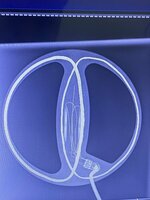
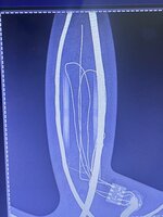
My aim here is to produce a bigger coil tuned for deeper larger objects relics cashes and such, attached in the thread are three X-rays of the standard coil that comes with the velox one, this coil operates on 17.kHz frequency.
A bigger aftermarket coil exists for this detector produced by the same manufacturer but is discontinued and very expensive if found i aim to produce an even bigger one for more depth and bypassing smaller objects.
I anyone has worked on self made coils, is an electronics engineer, understands how to gauge coil values and most of all identify the components on this pcb without breaking the resin on the coil i would love to get your take on this endeavour
I am new to the forums i joined in the hope of finding likeminded individuals that love to tinker and modify devices.
My aim here is to produce a bigger coil tuned for deeper larger objects relics cashes and such, attached in the thread are three X-rays of the standard coil that comes with the velox one, this coil operates on 17.kHz frequency.
A bigger aftermarket coil exists for this detector produced by the same manufacturer but is discontinued and very expensive if found i aim to produce an even bigger one for more depth and bypassing smaller objects.
I anyone has worked on self made coils, is an electronics engineer, understands how to gauge coil values and most of all identify the components on this pcb without breaking the resin on the coil i would love to get your take on this endeavour
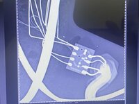
 interesting what about those components on the pcb board what do you think they are and also can this be upscaled to a bigger coil or the whole thing has to be reworked